01 Jul, 2025
Reliable Controller-to-Switch Isolation in Harsh Electrical Environments
Plastic Optic Fiber (POF) technology provides robust galvanic isolation and superior EMI/EMC immunity for mid-to-large drive applications operating in electrically noisy industrial environments. From IGBT and SiC driver systems to Smart Grid networking infrastructure, modern POF solutions deliver high-speed, reliable, and low-maintenance optical communication between switches, controllers, and industrial networks.
Designed for harsh environments and industrial temperature ranges, today’s POF transceivers support everything from PWM signal transmission to real-time Ethernet-based industrial communication protocols.
Let's see a list of relevant questions on galvanic isolation:
What Is Galvanic Isolation?
Galvanic isolation is a method of separating two electrical circuits so that no direct electrical current can flow between them, while still allowing signals or power to be transferred. The separation is typically achieved using technologies such as transformers, optocouplers, capacitive isolators, or fiber optics. In the attached reference, Plastic Optic Fiber (POF) is used to create a “digital bridge” that transfers data signals optically rather than electrically, providing complete electrical isolation between systems.
What is the purpose of a galvanic isolator?
The purpose of a galvanic isolator is to protect equipment, circuits, and users from unwanted electrical effects while still enabling communication or control between systems. Specifically, it is used to:
- Prevent dangerous voltage transfer between circuits
- Protect sensitive electronics from electrical faults
- Reduce electrical noise and electromagnetic interference (EMI/EMC)
- Eliminate ground loops
- Improve system reliability and safety
- In power electronics and drive systems, galvanic isolation protects low-voltage controllers from the high voltages and switching noise generated by devices such as IGBTs and SiC switches.
Why is galvanic isolation needed in mid-to-large drive applications?
Galvanic isolation is needed because many electronic systems operate at different voltage levels or in electrically noisy environments. Without isolation, unwanted currents or voltage spikes could travel directly between circuits and damage components or corrupt signals.
For example, in motor drives, smart grids, and industrial power systems, switching devices generate strong electrical and magnetic noise. The attached reference explains that POF links are used because they provide immunity to this EMI/EMC noise while safely isolating controllers from high-power switching electronics.
How does galvanic isolation works?
A galvanic isolator works by transferring signals or energy across an isolation barrier without a direct conductive connection.
In the reference document, the isolator works using Plastic Optic Fiber (POF):
- An electrical signal is converted into light by a transmitter (using an RCLED).
- The light travels through the plastic optical fiber.
- A receiver detects the light with photo-diodes and converts it back into an electrical signal.
- Because the signal crosses as light rather than electrical current, there is no direct electrical path between the two circuits.
The system also improves immunity to EMI by using differential photo-diode detection, which cancels out common electrical and magnetic noise. This allows clean, reliable communication even near high-power switching devices like IGBTs.
Galvanic Isolation And EMI/EMC Immunity between Switch and Controller in Mid-to-Large Drive Applications with Plastic Optic Fiber
Author - Michael O’Gorman, Application Engineering Manager
Introduction to Plastic Optic Fiber (POF)
Plastic Optic Fiber (POF) emerged in the late 1970s and found its first application in power electronics with the release by HP of connectors which provided a path to use POF as an isolation technology to provide both galvanic isolation between two PCBs as well as isolation from EMI/EMC. Today POF links are a key part of mid-range and large drives providing the protection needed by the controllers from the electronic noise generated by the switching technology of choice (Thyristors, IGBTs and SiC devices). Looking at the connectors it is not obvious that much has changed. The from factor looks identical but under the hood this technology has grown significantly to meet the demands of the 21st century Power Electronics Industry.
Under the hood new ASICs have revolutionized the performance taking the solutions from 40 kBd to 50 MBd with TX drivers fully integrated and enhanced EMI/EMC immunity.
Market Evolution and Industrial Temperature Requirements
Today this market is multi-sourced with four major manufacturers of the fiber (Mitsubishi-Rayon, Toray, Asahi-Kasei and Sino-Optic) as well as multiple global suppliers of the optical connectors/transceivers such as Firecomms. The RedLink connectors from Firecomms have seen significant developments that are not obvious to the casual observer. Comparing the original Plastic Optic Fiber and the original HP transceiver datasheets to the parts available today, the first item that a keen reliability engineer will spot is the increase in temperature range.
The original parts were limited to 0 to +70 °C. Today you have both fibers and transceivers rated to an industrial temperature range of operation in ambient temperatures of -40 to +85 °C and higher for some options. This development was driven by the demands of the applications. A locomotive sitting on a side-track in Alaska will experience severe cold while the same locomotive crossing the central desert of California at midday will need to tolerate very high ambient temperatures. This demand is equally relevant to Solar Energy farms located in deserts or Wind Farms located in our oceans not to mention HVDC technology in remote power plants as well as the SVG and SVC units required to balance the power lines in all of these installations. Thousands and thousands of hours of engineering and reliability testing has produced plastic optic fiber links suitable for use in 21st century Smart Grid applications.
RCLED Technology and Transmitter Improvements
A deeper dive under the hood will reveal that the majority of transmitters used today use RCLED technology instead of the original LED technology. The original LEDs were slow devices with long rise and fall times and they needed relatively high currents to generate the optical power needed to provide stable links with long lifetimes. With the arrival of
commercially available industrial Resonant Cavity LEDs (RCLED) in the early 2000’s the transceiver manufacturers were able to make faster devices which use a lot less current to achieve the same optical power levels. Today you can get 10 and 50 MBd transceivers that use a fraction of the current consumption required by the original 40kBd and 1MBd LED based transmitters to achieve the same optical powers. Reducing current is obviously important for saving the planet by reducing the energy demand of the devices built with these parts but also has a significant benefit to long term reliability as every reduction in current consumption results in a fourfold increase in transmitter lifetime. Increasing the product lifetime leads to lower OPEX and CAPEX, due to direct reduction in field maintenance costs. In summary the transmitters available today are faster, have less skew (less part to part variability), use less current to generate the same optical power, last longer and therefore require less maintenance.
Receiver Technology and CMOS ASIC Development
The improvements are not limited to the transmitter side of the link. The receiver end of the POF link has also seen significant development in the last 15 years. Originally, the HP receivers were based on Bi-CMOS technology with a single integrated photo-diode. Firecomms ASICs are designed on pure CMOS process nodes, that allows for integration of more intelligence into the receiver solution. These custom Firecomms ASICs integrate all of the functions necessary to convert the optical signal to a digital output signal. At the front end the physical interface uses a dual-photo-diode scheme to detect the light. A photo diode detects the light and a mirror photo-diode is screened from the light, both elements experience all of the electronic and magnetic fields emanating from the nearby switches, e.g. an IGBT.
The photo-diode signals are fed into a differential amplifier which cancels the common electronic/magnetic noise and as a result forwards the clean optical signal now converted to a clean electrical signal. The electrical signal is amplified, put through a comparator and finally through a line driver stage conditioning it for release to a TTL, LVTTL or LVDS data bus as a standard electronic signal. The receivers available today feature dual operation from both traditional 5V power supply rails as well as 3.3V supplies and can therefore interface directly to older TTL logic ICs as well as modern standard 3.3V based Micro-controllers, FPGAs, ASICs and PHY ICs. In summary, the receivers available today compared to an historic ROSA leverage CMOS based ASICS that have excellent EMI immunity thanks to the differential photo-diode front end, the fully integrated signals path and the ability to adapt automatically to the supply line and output the correct logic level for the next step in the signal path.
Fundamentally with the introduction of CMOS ASICs into both the transmitter to drive the RCLED and the receiver to cleanly detect the light, the POF transceiver today provides a true digital bridge from one electronic bus to another across a plastic optic fiber giving galvanic, electrical and magnetic noise field immunity from DC to 50 MBd with a minimal application circuit.
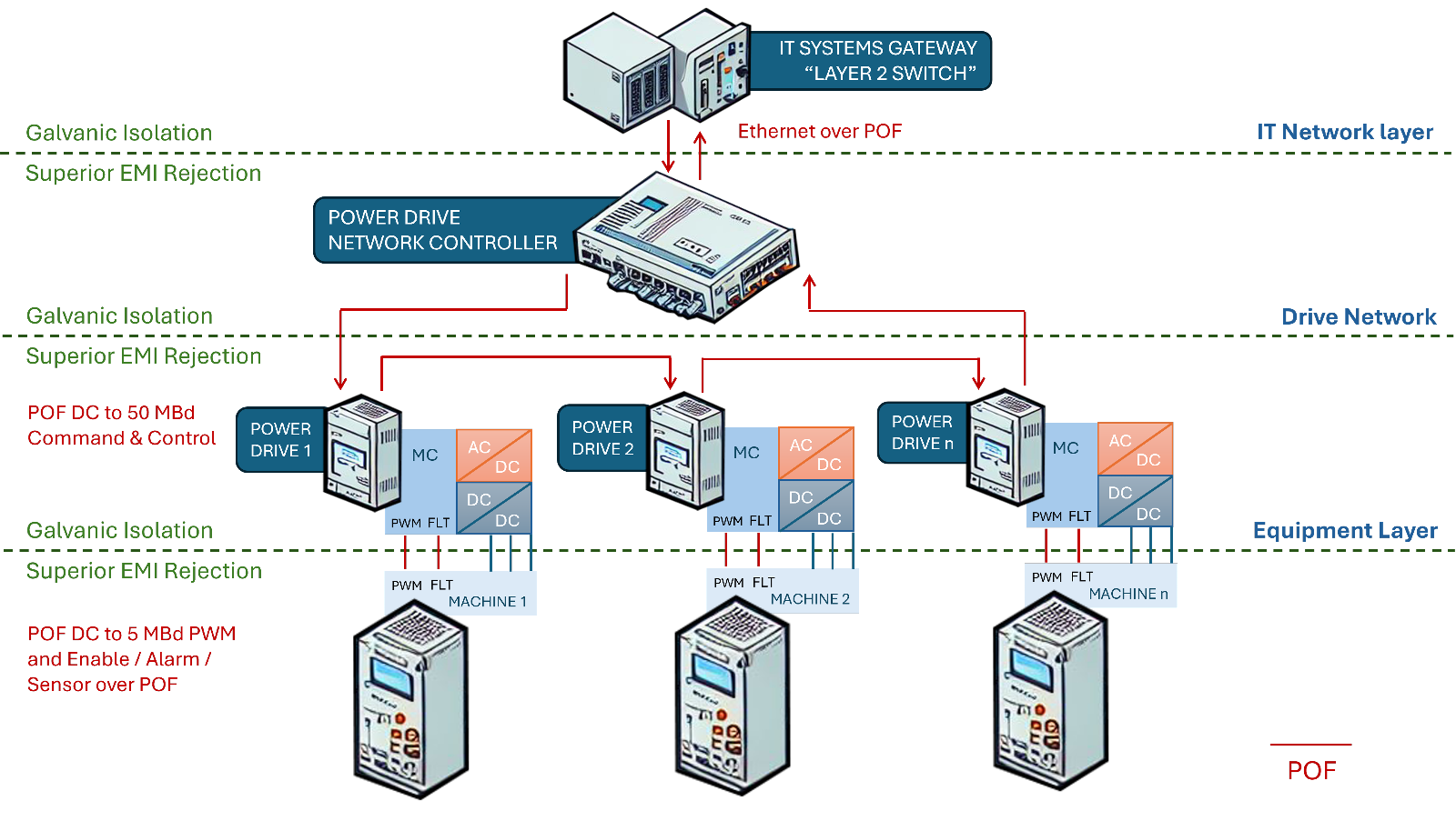
The introduction of ASICs integrated into the optical components, the digital bridges offers customers the possibility to use POF for galvanic isolation and EMI rejection not just in the equipment layer of their system but as illustrated in all three of the system layers from the equipment, to the networking of drives and with the Fast Ethernet devices even out to the IT layer providing protection between the drive network and the wider IT network.
PCB-Level Integration and Drive Networking
At a PCB level the digital bridges automatically configure to match the power rail available and by extension the correct logic levels of the PCB that they sit on. They can be used for alarm signals holding a static light on or light off for years and years without error or can be used in the traditional way for PWM delivery from drive controller to switch. However this technology has wider scope with the new higher speeds which can also be used to network the drives helping to co-ordinate multiple drives across a network of devices. The new generation of DC-50 MBd devices have extended the benefits of noise immunity beyond singular IGBT or SiC control to include the networking of multiple controllers with superior noise immunity that traditional copper wire cannot provide. The simple connectivity of POF with proven reliability can network any number of drives.
Beyond 50MBd, it is also important to note that POF can also support higher speed such as Fast Ethernet and right up to 250 MBd. The majority of FPGAs used today support a native LVDS port operating at 200 Mbps and this will interface directly to a POF transceiver offering fully duplex datacomms links supporting real time monitoring of power systems in locomotives, smart grids, and power monitoring in data-centers. The datacomms links over POF support real time protocols such as EtherCAT and Profinet as well as proprietary links.
To summarize, Plastic Optic Fiber and the humble HP connector have come a long way. Today, it can support not just a basic PWM signal between driver controller and thyristor but an array of IGBTs and SiC devices. The POF link can also be used in the next levels of control hierarchy, to network a number of drive controllers together for higher efficiency and again in the third layer where the drive network controller meets the wider IT system network. POF can offer real-time compatible links operating at internet speeds providing complete galvanic isolation between the IT systems and the electrical plant. All three layers of operating come with proven reliability, simple and robust fiber termination, eye safe visible red light, low current consumption and operation over industrial temperatures in harsh environments. Plastic Optic Fiber links are, therefore, ideal for use in 21st century Smart Grids.